In post [Indexing Cam Angles Comparison (1/2)], we explained how to calculate the displacement of indexer (hm) from number of stops (S) and the meaning of the indexing angle (bm). In this post, we will show how the rotary indexers with different indexing angles move.
We have 2 indexers. Both of them have S = 4, but the first indexer has bm = 120 deg. and the second indexer has bm = 240 deg.
The input shafts of both indexers rotate continuously at the same speed. The first indexer completes its indexing in 120 deg. while the second indexer takes longer time and completes its indexing in 240 deg. We can clearly see from the animation that the longer the indexing time, the smoother indexing motion (lower acceleration).
The indexer has many displacement profiles e.g. modified sine, modified trapezoidal, etc. But for the explanation, we will use cycloidal motion profile.
hm = displacement of the turret plate (deg.)
bm = indexing angle (deg.)
tm = indexing time (s) -- indexing time is proportional to indexing angle (bm)
Both indexers have same number of stops (same displacement hm) and same input velocity (w). So the relationship between velocities can be expressed as
Since the indexing time of the second indexer is 2 times the first one. The velocity of the second indexer then becomes half of the first one as can be seen in eq. 3
The maximum tangential acceleration of cycloidal profile when the input shaft rotates at a constant speed (constant w) can be expressed as ...
tm = indexing time (s) -- indexing time is proportional to indexing angle (bm)
Both indexers have the same number of stops (same displacement hm) and same input velocity (w). So the relation between accelerations can be expressed as
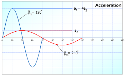
Since the indexing time of the second indexer is 2 times the first one. The acceleration of the second indexer then becomes 1/4 of the first one as can be seen in eq. 5 -- This is quite interesting. By selecting longer indexing angle (indexing time), we can reduce its acceleration by square of indexing time ratio.
In this example, the second indexer runs at only 25% tangential acceleration of the first indexer by selecting 2 times indexing angle. However, there will be less time during dwell period for other machine units to work with.
We have 2 indexers. Both of them have S = 4, but the first indexer has bm = 120 deg. and the second indexer has bm = 240 deg.
 |
| Indexers with bm=120 deg. and bm=240 deg. |
The indexer has many displacement profiles e.g. modified sine, modified trapezoidal, etc. But for the explanation, we will use cycloidal motion profile.
The cycloidal displacement profile can be expressed as ...
where:
h = displacement (deg.)
q = angle of the input shaft (deg.)where:
h = displacement (deg.)
hm = displacement of the turret plate (deg.)
bm = indexing angle (deg.)
 |
| Displacement diagram of 2 indexers with different indexing angles (bm) |
We can see from the displacement diagram that both curves have smooth continuous displacement. There is not much displacement at approximate 10% and 90% of the indexing angle.
- For bm = 120 deg.: 10% = 12 deg.
- Very small displacement within first 12 deg. and from 108 deg. to 120 deg.
- For bm = 240 deg.: 10% = 24 deg.
- Very small displacement within first 24 deg. and from 216 deg. to 240 deg.
This fact can be used for timing diagram design later.
Maximum velocity can be calculated from ...
where:
vmax = maximum velocity (deg./s)
hm = displacement of the turret plate (deg.)
w = angular velocity of the input shaft (rad/s)vmax = maximum velocity (deg./s)
hm = displacement of the turret plate (deg.)
tm = indexing time (s) -- indexing time is proportional to indexing angle (bm)
 |
| Velocity diagram of 2 indexers with different indexing angles (bm) |
Since the indexing time of the second indexer is 2 times the first one. The velocity of the second indexer then becomes half of the first one as can be seen in eq. 3
The maximum tangential acceleration of cycloidal profile when the input shaft rotates at a constant speed (constant w) can be expressed as ...
where:
amax = maximum tangential acceleration (deg./s2)
hm = displacement of the turret plate (deg.)
w = angular velocity of the input shaft (rad/s)amax = maximum tangential acceleration (deg./s2)
hm = displacement of the turret plate (deg.)
tm = indexing time (s) -- indexing time is proportional to indexing angle (bm)
Both indexers have the same number of stops (same displacement hm) and same input velocity (w). So the relation between accelerations can be expressed as
Since the indexing time of the second indexer is 2 times the first one. The acceleration of the second indexer then becomes 1/4 of the first one as can be seen in eq. 5 -- This is quite interesting. By selecting longer indexing angle (indexing time), we can reduce its acceleration by square of indexing time ratio.
 |
| Acceleration diagram of 2 indexers with different indexing angles (bm) |


