Ezy Mechanic

Ezy Mechanic | Machine components and linkages design made easy.

Saturday, August 8, 2015

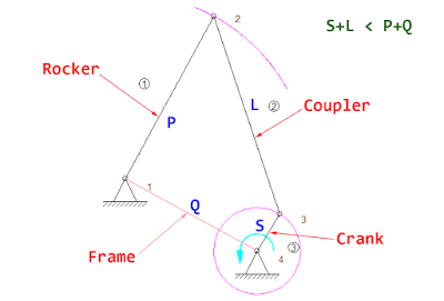
Grashof's Criterion: Crank-Rocker Four-Bar Mechanism

with 0 Comment
Grashof's criterion for Double Crank Four-Bar Mechanism is almost the same as Crank-Rocker Mechanism. They're both defined as S+L < P+Q. The difference is on the location of the shortest link (S). For double crank mechanism, S must be on the ground link (frame). But for the crank-rocker, S will be on the side link and it must be the input link. We then move the shortest link from the frame to the side link on LH. With the help of SAM...

Wednesday, August 5, 2015

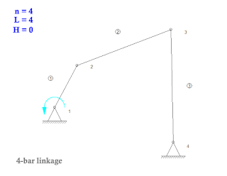
Grashof's Criterion: Four-bar Mechanism Double Crank

with 0 Comment
One of the most commonly used linkages is the four-bar linkage. It consists of 3 moving links and 1 ground link (also called a frame). There are 4 pin joints connected between those links. And from Gruebler's Equation, it's the mechanism with 1 degree of freedom (1DOF) which requires only 1 actuator to drive and control position of all linkages. The four-bar mechanism consists of the following components. Four-bar mechanism components The...

Wednesday, July 29, 2015

Gruebler's Equation for calculating Degrees of Freedom of the Mechanism

with 0 Comment
Mechanism with 1 degree of freedom To design the mechanism, the first thing we should check is the number of degrees of freedom (DOF) of the mechanism. The degree of freedom is the number of inputs required to control the position of all links of the mechanism. It's usually the number of actuators needed to operate the mechanism.  We can use Gruebler's equation to calculate the number of degrees of freedom of the mechanism...

Stiffness of a lever with eccentric loading - Part 2

with 0 Comment
Let's continue from the previous post. We clearly see that the small post must be shortened because it the weakest point and creates torsional load to the lever arm. We're going to try redesigning with a bent lever arm so that the loading point stays in the middle of the center line of the arm. Lever bending to eliminate torsion The eccentric distance "r2" is shorter than previous design (r1). It's now the eccentric dimension with respect...

Tuesday, July 28, 2015

Stiffness of a lever with eccentric loading - Part 1

with 0 Comment
A lever is a mechanical part that has arms and a fixed pivot used to transmit torque. The cross section of the arm is usually a rectangular shape which makes it stiff against bending. However, its stiffness may become lower if the loading point is not on the right place. We're going to see the effect of torsion on the lever with the improvement idea. The following picture is the components of a general cam and lever system. The lever...

Monday, July 27, 2015

Stiffness of a welded straight square tube

with 0 Comment
To modify or improve process of the existing machine in a production line may have some constraints regarding available spaces. There may be other moving objects or fixed parts which obstruct mounting of newly design parts. The part that comes later may be more complex since it has a limited space for mounting. The green support, design C from earlier post, is the example. Part with other object occupied spaces This is the side view...

Saturday, July 25, 2015

Stiffness comparison of welded parts - Part 4

with 0 Comment
As we can see from previous post that design C is still the best choice since it's light-weight and relatively rigid compared to other designs. Design E is the most stiff design but it's also the most heavy design. Let's continue with the remaining 2 designs with 4 ribs at the mounting base to see whether they're better than design C or not. Finite Element Analysis result: Displacement of Design G The weight of this design is in the...

Stiffness comparison of welded parts - Part 3

with 0 Comment
There are a lot of designs of welded parts which are commonly seen. The design A as shown in previous post are one of the examples. However, there are some more examples which may seem to be much better than design C. Let's have a look at these 5 more designs and see how stiff they are. Normally, to make the welded parts more rigid, we have to add some more materials. This usually increases the weight (mass) of the part which, in most...

Thursday, July 16, 2015

Stiffness comparison of welded parts - Part 2

with 0 Comment
From [Stiffness comparison of welded parts - Part 1], we have 3 different designs of supports subjected to the same loads which we're going to compare their stiffness. Let's start with the Finite Element Analysis (FEA) model of design A. Finite element analysis (FEA) model of Design A The mounting plate on the right is constrained so that there is no displacement in x, y and z directions. The flange on the left is subjected to face...

Wednesday, July 15, 2015

Stiffness comparison of welded parts - Part 1

with 0 Comment
In the machine, we usually make parts to support other machine components from standard steel profiles because they are relatively low cost. In this post, we're going to see how different constructions affect the stiffness of the welded parts. We have 3 different constructions of supports as shown in the picture. Supports with different constructions The constructions are slightly different. A -- typical welding (mass = 0.9 kg) B...

Tuesday, July 14, 2015

Moment of inertia

with 1 comment
The Moment of Inertia or Mass Moment of Inertia is the measure of a body's resistance to change in it's rotational speed. The moment of inertia must be specified with respect to a chosen rotational axis. The moment of inertia depends on the body's mass distribution and the rotational axis chosen. The larger moment of inertia requiring more torque to change the body's rotational speed. A point mass The moment of inertia is the mass times...

Total Pageviews

SEO Stats powered by MyPagerank.Net

Disclaimer

Every care has been taken to ensure the accuracy of the information but no liability can be accepted for any loss or damage whether direct, indirect or consequential arising out of the use of the information or calculation sheets from our blog.
Powered By Blogger