Ezy Mechanic

Ezy Mechanic | Machine components and linkages design made easy.

Wednesday, July 8, 2015

Example of rotary indexer sizing calculation for table plate drive application (3/3)

with 0 Comment
Step 4 : Rotary Indexer Model Selection
Minimum Follower Wheel Pitch Diameter (Credit : Sankyo)

  • Recommended Size of Rotary Indexer can be estimated. By calculate Radius of Gyration divide by Follower Wheel Pitch Radius, this value should be less than 5 (this value may vary depend on difference manufacturer)
Recommended Follower Wheel Pitch Radius of Rotary Indexer
  • Minimum Follower Wheel Pitch Radius, [PRmin] = 427/5 = 85.424 ≈ 85.4 mm
  • Then, Minimum Follower Wheel Pitch Diameter, [PDmin] ≈ 85.4 x 2 ≈ 171 mm
  • Recommended Size of Rotary Indexer also can be estimated by another method. By calculate Table Diameter divide by center distance between input & output shaft, this value should be less than 7 (this value may vary depend on difference manufacturer)
Distance Between Input & Output Shaft
Recommended Center Distance between Input & Output Shaft of Rotary Indexer
  • Then, Minimum Distance Between Input & Output Shaft, [CDmin] = 1000/7 = 142.857 ≈ 143 mm
  • Total Output Torque for Indexer Selection, [Tt select] = Tt x SF = 307.271 x 1.2 = 368.726 ≈ 369 N.m @ Input Shaft(camshaft) Speed 60 rpm
Thus, Select Indexer that Dynamic Rated Output Torque [Top] is more than 369 N.m at input shaft speed more than 60 rpm, 8 stops, Indexing Angle 270 degree, MS motion curve, minimum center distance between input & output shaft 143 mm and minimum follower wheel pitch diameter 171 mm
Step 5 : Gear & Motor Selection
Find the maximum torque on gear output shaft at working shaft speed
  • In this case, gear is directly connect to the rotary indexer. Then the maximum torque on gear output shaft is equal to the camshaft torque of rotary indexer
  • The camshaft torque of rotary indexer[Tc] is determined by following formula:
Rotary Indexer Cam Shaft Torque
  • Internal Indexer Inertia Torque, [Toi] = 2.943 N.m (from rotary indexer manufacturer data)
  • Camshaft Friction Torque, [Tx] = 16.677 N.m (from rotary indexer manufacturer data)
  • Maximum Camshaft Torque Coefficient, [Qm] = 0.987 (This is standard value, find the Qm for Modified Sine Cam Curve from Cam Curve Characteristic Table)
  • Then, Camshaft Torque, [Tc] = 87.552 N.m @ camshaft speed 60 rpm (This is the torque at input shaft of rotary indexer which is equal to torque at output shaft of gear)
Next, calculate the equivalent camshaft torque for gear selection [Tce select] by considering of operating condition & safety factor
  • Calculated Operation Factor, [f] = 1.8 (Calculate from type of load(steady or shock load), operating hours per day, frequency of starts/stops, ambient temperature, type of lubrication or others factor. Please check gear manufacturer information. In this case use 1.8)
  • Then, Tce select = Tce x f x SF = 87.552 x 1.8 x 1.2 = 189.113 N.m @ Output Shaft Speed 60 rpm
Calculate Gear Input Shaft Torque
  • Gear Ratio, [ig] = 10.33 (Check from gear manufacturer info.)
  • Gear Input Shaft Speed, [Ng] = Nrpm x i= 60 x 10.33 = 619.8 ≈ 620 rpm
  • Gear Running Efficiency, [Effg] = 92% (Check from gear manufacturer info.)
  • Gear Input Shaft Friction Torque, [Txg] = 0.9 N.m (Check from gear manufacturer info.)
  • The Gear Input Shaft Torque[Tg] is determined by following formula:
Gear Input Shaft Torque
  • Gear Input Shaft Torque, [Tg] = 10.113 N.m @ Input Shaft Speed 620 rpm
Calculate Motor Torque
  • Motor Revolution per Minute, [Nmotor] = 1730 rpm (from motor manufacturer data)
  • Gear Ratio Required, [ireq] = Nmotor / Nrpm = 1730 / 60 = 28.833
  • Pulley Speed Ratio, [ipulley] = Ireq / I= 28.833 / 10.33 = 2.791 ≈ 2.8 (←if very close to 1, motor can be mounted directly to gear, then set Effpulley = 100% & Txp = 0
Table Drive Application with Pulley (Credit : Sankyo)
  • Pulley Running Efficiency, [Effpulley] = 90% (estimated)
  • Pulley Shaft Friction Torque, [Txp] = 2 N.m (estimated)
  • The Motor Torque [Tmotor] is determined by following formula:
Motor Torque
  • Then, Motor Torque, [Tmotor] = 10.003/(2.791 x 0.9) + 2 = 6.026 N.m @ Speed 1730 rpm
Calculate Motor Power
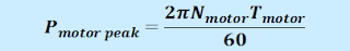
  • The Peak Motor Power [Pmotor peak] is determined by following formula:

  • Then, The Peak Motor Power [Pmotor peak] = 2 x 3.1416 x 1730 x 6.026 / 60 = 1091.617 Watt ≈ 1.092 Kw
Calculate Motor Power for Motor Selection
  • Power for Motor Selection, [Pmotor sel] = Pmotor peak x SF = 1.092 x 1.2 = 1.310 Kw
Then,  select gear that maximum continuous output torque is more than 189 N.m at output shaft speed more than 60 rpm, gear ratio 10.33
Motor power 1.31 Kw at speed 1730 rpm

Ratio of pulley between gear and motor 2.8


Example of rotary indexer sizing calculation for table plate drive application (2/3)

with 0 Comment
Calculations
Rotary Indexer with Dial Plate Driving Application Torque Diagram

Step 1 : Moment of Inertia Calculations
Dial Plate Inertia
  • Stations Inertia, [Ist] = 160 x ((450/1000)/2)^2 = 32.400 Kg.m2
Stations Inertia
  • Additional Part Inertia, [Iadd part] = 8 x ((300/1000)/2)^2 = 0.720 Kg.m2
Additional Parts Inertia
  • If there are others group of additional parts, do the same method.
  • Total Moment of Inertia, [Itotal or ∑MK2] = 5.380 + 32.400 + 0.720 = 38.500 Kg.m2
Total Inertia
  • GD2 = 38.500 x 4 x 9.81 = 1510.739 N.m2
GD Square
  • Total Moving Mass, [∑M] = 43.040 + 120 + 8 = 211.040 Kg.
Total Moving Mass
  • Radius of Gyration, [K] = (Itotal/∑M)^1/2 = 427.118 mm
Radius of Gyration
Step 2 : Maximum Angular Acceleration Calculation
Cam Curve Characteristic Value

  • From the table, find the Dimensionless Maximum Angular Acceleration for Modified Sine Cam Curve, [Am] = 5.53
  • Then, the Maximum Angular Acceleration, [am] = 0.785 / 0.75^2 x 5.53 = 7.721 rad/sec2

Maximum Angular Acceleration
Step 3 : Required Torque Calculations
Torque on Rotary Indexer
  • Inertia Torque at Index Shaft, [Ti] = 38.500 x 7.721 = 297.271 N.m

  • External Friction Torque to Indexer, [Tf] = 10 N.m (Such as outboard support bearings, assume to 10 N.m)
  • Work Torque, [Tw] = 0 N.m (Indexer is doing work such as lifting parts, assume to 0)
  • Total Output Torque, [Tt] = 297.271 + 10 + 0 = 307.271 N.m
Total Torque at Output Shaft


Friday, July 3, 2015

Example of rotary indexer sizing calculation for table plate drive application (1/3)

with 1 comment
Indexing System Information
Physical Properties Info.
Rotary Indexer with Dial Table Driving Application

Dial Table Info.
  • Diameter, [Ddial] = 1000 mm
  • Thickness, [Y] = 20 mm
  • Material = Aluminum (Density 0.00274 g/mm3)
Mass of dial table
  • Then Table Mass, [Mdial] = 43.040 Kg.
Station Info.
  • Number of Stations, [Nstations] = 8 stations
  • Mass per Station, [Mstation] = 20 Kg/staion
  • Then Total Station Mass, [SMstations] = 8 x 20 = 160 Kg
  • Rotating Radius to Station Center, [Rst] = 450 mm (If the station is large or complex shape, a radius of gyration of each station should be calculated.)
Additional Part Info. (The same part at the same rotation radius)
  • Number of parts, [Nadd part] = 4 parts
  • Part Mass, [Madd part] = 2 Kg/part
  • Total Additional Part Mass, [SMaddpart] = 4 x 2 = 8 Kg
  • Rotating Radius to Part Center, [Radd part] = 300 mm (If the part is large or complex shape, a radius of gyration of each part should be calculated.)
  • If there are others group of additional parts, do the same method.
Movement Info.
Rotary Indexer
Rotary Indexer Movement Term
  • Number of Stops, [S] = 8 stops
Displacement per 1 index
  • Dial Plate Displacement per Index, [hm] = 2 x 3.1416 / 8 = 0.785 rad
  • Indexer Input Shaft Cycle, [T] = 1 sec (Assume to 1 second, this can be adjusted later)
Indexing Rate
  • Indexing Rate, [Nrpm] = 60/1 = 60 rpm
  • Indexing Period, [Bm] = 270 deg (Assume to 270 degree, should be taken as long as possible for smoother movement. Please check to the manufacturer information)
Indexing Time
  • Indexing Time, [tm] = 270/360 x 60/60 = 0.750 sec
Dwell Time
  • Dwell Time, [tdwell] = 1 - 0.750 = 0.250 sec
  • Required Dwell Time, [tdwell required] = 10 sec (This is actual required dwell time according to the working process.)
  • In case of tdwell required > tdwell  we can use clutch and brake to extend the dwell period, but if tdwell required < tdwell that mean we can reduce tdwell to be the same as tdwell required
  • Reducing tdwell required can be consider in 2 cases. Reducing indexer input shaft cycle [T] or Increasing indexing period [Bm].
  • This case,   tdwell required > tdwell
Motor stop time
  • Input Shaft Stop Time, [tstop] = 9.750 sec
Machine cycle time
  • Machine Cycle Time, [Tmachine] = T + tstop = 1 + 9.750 = 10.750 sec
  • Machine Speed, [Speedmachine] = 3600/10.750 x 8/8 = 334.884 UPH
Machine Speed
Displacement VS Indexing Angle Timing
Displacement VS Indexing Angle

  • Cam Curve : Modified Sine (assumed, please check from rotary indexer manufacturer data)
  • Safety Factor, [SF] = 1.2
  • Operating Condition : 24 Hrs running, Steady load, Starts/stops 2 times per hour, Ambient temperature 30 C, Without cooling fan


Rotary indexer sizing calculation for table plate drive application

with 0 Comment
In this post we will explain how to calculate the size of rotary indexer, gear & motor for dial plate table application.
Rotary Indexer with Table Plate Driving Application

There are 2 things we need to know for the calculation
  1. Physical properties info.
  2. Movement info.
Physical properties information of movement part is data we need to use for calculate the total moment of inertia of the moving system. It consists of dial plate diameter, thickness, density for calculate mass, the number of stations, station mass, station radius to rotation center, etc.

Movement information is data we need for find the maximum angular acceleration of the moving system. It consists of number of stops, RPM of rotary indexer input shaft, indexing angle, dwell time, type of cam curve, etc.

After we know the value of the total moment of inertia and the maximum angular acceleration of the moving system, we can easily calculate the required torque for driving the system. Then we can select the rotary indexer that match the required torque.

For selection of gear, we can use this required torque at output shaft of indexer to calculate the required torque of input shaft of the indexer by using maximum camshaft torque coefficient, internal indexer inertia torque, camshaft torque from indexer manufacturer data, number of stops and indexing angle. When we know the torque required at indexer camshaft(which is output shaft torque of gear), we can select the gear.

For the motor selection, we have calculate the gear input shaft torque by converting gear output shaft torque with gear ratio. Then use this torque for calculate the motor power required.

Wednesday, July 1, 2015

Indexers with single dwell (1-dwell) VS double dwell (2-dwell)

with 0 Comment
To configure a rotary indexer, there are several parameters to decide such as number of stops (S), indexing angle (bm), maximum output torque, etc. In this post, we will show one more parameter which may affect the design if misunderstood. It's a number of dwell. In most cases, we use 1-dwell (single dwell) for the application. The indexer performs single index within the designated indexing angle and wait (dwell) until cycle complete.

However, for some indexer models, there will be the option to select 2-dwell cam type (double dwell, double indexes). Or there may be only 2-dwell version especially for the models which have large number of stops and long indexing angle e.g. S=20, bm = 210 deg.

2-dwell indexer will perform differently from 1-dwell indexer though they're both having the same S and bm. The 1-dwell indexer will index only one once per each full revolution of the input cam shaft. But the 2-dwell indexer will index 2 times and also stop 2 times per each revolution of the input cam shaft as can be seen in the following displacement diagram.
diagram explaining difference between 1-dwell and 2-dwell rotary indexers
Displacement diagram of both 1-dwell indexer and 2-dwell indexer
The 2-dwell indexer divides displacement into 2 halves. The first half take half indexing angle (bm/2) to rotate the output shaft to next station. The dwell angle is also divided by 2. It has 2 times displacement compared with the displacement of the 1-dwell cam as can be seen in the red line on the above chart.

In this post, we use indexers with following parameters for comparison.
They both have ...
  • Number of stops, S = 12 stops. So the displacement (hm) becomes hm = 360/12 = 30 deg.
  • Indexing angle, bm = 210 deg.
  • Same input shaft speed (w)
1-dwell and 2-dwell rotary indexers
1-dwell and 2-dwell rotary indexers with S = 12 and bm = 210 deg.
According to the explanation of the 2-dwell cam motion, the second indexer will perform 2 indexes and 2 dwells per 1 turn of the input shaft. The actual indexing angle will become bm/2 = 210/2 = 105 deg. Therefore, the 2-dwell indexer takes 105 degrees to complete the first index with output shaft displacement (hm) of 30 deg. Then it waits (dwell) until the input shaft angle reaches 180 deg. and it restart the next indexing from 180 deg. to 180 + 105 = 285 deg. After that, it waits until the input shaft complete its turn. Then the next cycle starts...

Here is the animation of how both indexers move.
animated gif: how 1-dwell and 2-dwell rotary indexers move
How 1-dwell indexer and 2-dwell indexer move
Watch the following video for the animation made with Unigraphics NX4 motion simulation.


Monday, June 29, 2015

Indexing Cam Angles Comparison (2/2)

with 0 Comment
In post [Indexing Cam Angles Comparison (1/2)], we explained how to calculate the displacement of indexer (hm) from number of stops (S) and the meaning of the indexing angle (bm). In this post, we will show how the rotary indexers with different indexing angles move.

We have 2 indexers. Both of them have S = 4, but the first indexer has bm = 120 deg. and the second indexer has bm = 240 deg.
animated gif: how different indexing angles move
Indexers with bm=120 deg. and bm=240 deg.
The input shafts of both indexers rotate continuously at the same speed. The first indexer completes its indexing in 120 deg. while the second indexer takes longer time and completes its indexing in 240 deg. We can clearly see from the animation that the longer the indexing time, the smoother indexing motion (lower acceleration).

The indexer has many displacement profiles e.g. modified sine, modified trapezoidal, etc. But for the explanation, we will use cycloidal motion profile.

The cycloidal displacement profile can be expressed as ...
Cycloidal displacement formula... (eq. 1)
where:
h = displacement (deg.)
q = angle of the input shaft (deg.)
hm = displacement of the turret plate (deg.)
bm = indexing angle (deg.)
displacement chart of 2 different indexing angles
Displacement diagram of 2 indexers with different indexing angles (bm)
We can see from the displacement diagram that both curves have smooth continuous displacement. There is not much displacement at approximate 10% and 90% of the indexing angle.
  • For bm = 120 deg.: 10% = 12 deg.
    • Very small displacement within first 12 deg. and from 108 deg. to 120 deg.
  • For bm = 240 deg.: 10% = 24 deg.
    • Very small displacement within first 24 deg. and from 216 deg. to 240 deg.
This fact can be used for timing diagram design later.

Maximum velocity can be calculated from ...
maximum velocity of cycloidal cam profile... (eq. 2)
where:
vmax = maximum velocity (deg./s)
hm = displacement of the turret plate (deg.)
w = angular velocity of the input shaft (rad/s)
tm = indexing time (s) -- indexing time is proportional to indexing angle (bm)
chart of velocity cycloidal cam profile, 2 different indexing angles
Velocity diagram of 2 indexers with different indexing angles (bm)
Both indexers have same number of stops (same displacement hm) and same input velocity (w). So the relationship between velocities can be expressed as
equation: new velocity according to new indexing angle... (eq. 3)
Since the indexing time of the second indexer is 2 times the first one. The velocity of the second indexer then becomes half of the first one as can be seen in eq. 3

The maximum tangential acceleration of cycloidal profile when the input shaft rotates at a constant speed (constant w) can be expressed as ...
equation: max acceleration of cycloid cam profile... (eq. 4)
where:
amax = maximum tangential acceleration (deg./s2)
hm = displacement of the turret plate (deg.)
w = angular velocity of the input shaft (rad/s)
tm = indexing time (s) -- indexing time is proportional to indexing angle (bm)

Both indexers have the same number of stops (same displacement hm) and same input velocity (w). So the relation between accelerations can be expressed as
equation: new acceleration according to new indexing angle... (eq. 5)

Since the indexing time of the second indexer is 2 times the first one. The acceleration of the second indexer then becomes 1/4 of the first one as can be seen in eq. 5 -- This is quite interesting. By selecting longer indexing angle (indexing time), we can reduce its acceleration by square of indexing time ratio.
acceleration profile of 2 different indexing angles
Acceleration diagram of 2 indexers with different indexing angles (bm)
In this example, the second indexer runs at only 25% tangential acceleration of the first indexer by selecting 2 times indexing angle. However, there will be less time during dwell period for other machine units to work with.

Indexing cam angles comparison (1/2)

with 0 Comment
In post [Rotary Indexer For Indexing Motion], we explained the meaning of indexing with the example of displacement and velocity diagram to give an idea how the indexing mechanism works. We also showed the location of input and output shafts of the rotary indexer. In this post, we're going to see how both shafts work and the meaning of indexing angle.

rotary indexer, turret, gear and motor
Geared motor and Turret plate connected to the rotary indexer
Basic equipment setup of indexing system is as shown in the picture. The input shaft of the rotary indexer is connected to the geared motor or other drive components e.g. pulley, gear, etc. In this example, we use a "hollow shaft" geared motor which allows indexer's input shaft to insert directly into the hollow gear shaft without using any shaft couplings. But they must be carefully align in order to avoid misalignment between shafts.

At the output side of the rotary indexer, the output shaft or flange can be mounted to a turret plate. There will be tools mounted on the turret plate at the same P.C.D. (pitch circle diameter). The tool at each station is usually work-piece holder. When the turret plate indexes, it will transfer the work-piece from one station to another station in order to complete all required processes at different stations.

Indexing motion from the rotary indexer doesn't require stopping of the motor since it has internal construction with cam and rollers that generate indexing motion at the output shaft while the input shaft runs continuously. As a machine designer, to select the right indexer for the application, the first thing to do is to select number of stations. Usually we will provide additional spared positions for future improvement i.e. if required number of stations is 6, we may select 8 stations instead.

Number of stations is usually "number of stops (S)" on the indexer. In the following picture, the indexer has number of stops = 4. In each turn of the input shaft (or geared motor's shaft), the output shaft (turret plate) moves 1/4 turn. Therefore, the displacement of the turret plate (hm) in degree can be calculated using:

hm = 360/S

where:
hm = displacement of the turret plate (deg.)
S = number of stops
indexing angle, displacement of turret and number of stops
Number of stops (S), indexing angle (bm) and displacement (hm)
Hence, the displacement of the turret (hm) is 360/4 = 90 deg. The displacement is also an important factor of the acceleration which we we explore more in later posts.

The indexing angle (bm) is the total angle at the input shaft to rotate the output shaft (turret) to another station. If the rotary indexer has S=4 and bm = 120 deg., it means that when the input shaft turns 120 deg., the turret will completely turn from one station to another with the displacement of 90 deg.

See how different indexing angles move in the next post.

Total Pageviews

SEO Stats powered by MyPagerank.Net

Disclaimer

Every care has been taken to ensure the accuracy of the information but no liability can be accepted for any loss or damage whether direct, indirect or consequential arising out of the use of the information or calculation sheets from our blog.
Powered By Blogger